在超高磁场磁导转向医学成像
 A clinical scenario of UHF actuation. The surgeon manually steers the guidewire using the magnetic fields inside the MRI scanner by observing real-time feedback from MRI images. (B to D) Guidewire bending by insertion to the MRI scanner for different magnetization configurations. The guidewire with three different configurations is presented: parallel (B), perpendicular (C), and antiparallel (D) configurations. The guidewire at a different stage of motion is overlaid. The MRI scanner's magnetic field direction is shown with an arrow. The insertion direction is shown with double arrows. (E and F) Guidewire bending by a rotation platform for parallel and perpendicular configurations. The rotating magnetic field direction shows the platform rotation. The parallel configuration rotates the guidewire tip around the MRI's magnetic field direction. The perpendicular configuration rotates the guidewire perpendicular to the MRI's magnetic field. The guidewire at a different stage of motion is overlaid. (G) Base twist actuation of the guidewire with a perpendicular magnet. The base twist is shown with a rotational arrow. The guidewire at a different stage of motion is overlaid. (H) In situ magnetization switching from antiparallel to parallel configuration during an insertion inside a constrained space. The guidewire is initially in the antiparallel configuration and leans over the solid wall during insertion into the MRI scanner due to the magnetic torque. Later, the magnetization direction switches and aligns with the MRI field. (I) The dual-magnet guidewire in parallel, perpendicular, and antiparallel configurations. The magnetization direction is shown for each separate configuration. Credit: Science Advances (2023). DOI: 10.1126/sciadv.adg6438")
物理学家和工程师们可以通过使用远程操纵磁驱动导磁性引导微创医疗程序的范围。磁转向策略目前限于低磁场,从而防止他们的医疗系统集成操作超高字段,包括磁共振成像(MRI)扫描仪。现在一项新的研究发表在科学的进步,穆罕默德Tiryaki和一个研究小组在物理情报部门,生物医学工程和医学在德国,瑞士和土耳其,开发了一种磁导设计与指导策略超高字段。
演示了一个广泛的研究范围,与原位re-magnetization的潜力。结果说明操舵磁原理的指导钕磁铁临床前和光纤棒磁共振成像扫描仪。新开发的超高场磁驱动框架可以促进新一代磁自动化功能在临床磁共振成像扫描仪。
推进核磁共振成像(MRI)系统
尽管长达十年的发展的方法核磁共振成像技术相比有缺点x射线透视。x射线透视的电离无辐射的性质和其优越的软组织对比,使其成为一个更高级的替代。核磁共振成像系统目前工作区面积有限的扫描仪和它的低分辨率,导致一系列的新提议改善的方法。
例如,一个完全可以集成远程MRI-powered驱动方法铁磁体永磁直观的三维(3 d)转向。然而,该方法需要实时软件访问和添加函数在核磁共振扫描仪。在这工作,Tiryaki和他的同事们提出了一个超高磁导领域转向战略核磁共振扫描仪和展示了其生理上的转向能力相关的3 d与动脉血管幻影流,以及在核磁共振扫描肾的动物模型。
磁化永久磁铁在超高字段
永久磁铁等钕磁铁中常用的磁驱动高磁转矩和力传输在低磁场。开发永久磁铁与一个常数磁铁的磁化向量对齐容易轴在低磁场。而物理学家研究了永久磁铁的磁性理论在超高领域,他们仍然调查期间概念的影响自动磁驱动。
例如,在超高字段,永久磁铁假设形式的软磁铁。因此团队研究了磁化向量和计算永磁体磁力和扭矩作用。他们专注于散装钕磁铁,用振动样品磁强计演绎磁性材料常数,和研究的影响磁滞,以验证磁化的力量。
在核磁共振成像扫描仪中磁驱动和导设计
Tiryaki和他的同事测量了磁场和磁场梯度MRI扫描仪模型中磁转矩和力。他们计算了磁化角和扭矩作用于永磁在超高字段和调查相关的设计灵活的构建,形成了弹性导丝的核心,刚度和优化的应用磁导和机动灵活的身体磁驱动系统。
该团队使用开源软件,开发了一个Cosserat杆模型动态模拟模拟导丝的形状,包括弹性和引力理解对MRI磁场力和扭矩的影响。他们进行弯曲模拟验证杨氏模和其他参数基本导动态主动使用磁导。
 Magnetization at low fields, B < 0.1 T. The red and blue colors represent the direction of the easy axis (C). (B) Magnetization at high fields, B >> 0.1 T. The permanent magnet is magnetized substantially by the external magnetic field. (C) Magnetization curves of the cylindrical neodymium magnet measured inside a vibrating sample magnetometer at different θ. The magnet's magnetization in the x direction is measured, while the magnetic field is swept from 0 to 1.8 T in the x direction. (D) Magnetization vector alignment as a function of the easy axis alignment at different external field strengths. (E) Magnetic fields and gradients in the x direction of the MRI scanner. (F) Model-based magnetic torque acting on the cylindrical magnet as a function of the magnet orientation. The magnet is in its saturation regime for the solid lines and nonsaturated regime for the dashed lines. The direction of the torque is shown on the schematic. (G) Magnetic force as a function of the magnet position in the MRI scanner for different magnet orientations. The solid lines represent the force estimated with the magnetization model using the MRI magnetic field and gradient measurements. The dashed lines are the linear model estimation in the nonsaturated region. The dots are the force sensor measurements in the experiments. (H) The discretized Cosserat rod model, including the magnetic actuation. (I) Schematic of the magnetic actuation simulations. (J and K) The maximum rotation and rotation range in the simulations as a function of the guidewire thickness. Credit: Science Advances (2023). DOI: 10.1126/sciadv.adg6438")
磁转向模式和原位磁化
科学家们研究了各种各样的自动化磁驱动系统高自由度来实现磁导转向较低的领域。在缺乏高自由度、磁驱动系统之间的相互作用和超高字段导致阻塞在核磁共振成像扫描仪中转向置入导丝。团队因此研究导理解这种效应的基本配置和放置永久磁铁平行,垂直,反平行的导小费。
Tiryaki和同事探讨多种驾驶模式与手动导丝插入在磁共振扫描仪来执行各种各样的导航任务。原位re-magnetization在超高字段的概念导致了一个更有趣的磁导设计与双重稳定,有两个永久磁铁导的提示进行各种转向实验在一个二维平面。
 Schematic illustration of the obstacle avoidance experimental setup. The obstacles are placed in the robotic platform with remotely controlled motion in the x direction and yaw angle. The guidewire is inserted into the platform through the insertion point, and an operator manually controls the insertion and twist of the guidewire by hand at the entrance of the MRI scanner bore. The same platform is used for demonstration with three different magnetic configurations. (B) Obstacle avoidance with guidewire with a parallel magnet. The guidewire is steered to three target points shown in (i) using the platform rotation and guidewire insertion at 7 T. The magnetic gradient is used as an assistive force in (iv). (C) Obstacle avoidance experiment with a guidewire with a perpendicular magnet. The guidewire is steered to three target points shown in (i) using the platform motion in the x direction and the base twist. The operator controlled the bending of the guidewire through the magnetic field strength. The platform angle is kept the same throughout the navigation. (D) Obstacle avoidance with guidewire with an antiparallel magnet. The guidewire is steered to three target points shown in (i) using the platform motion in the x direction, base twist, and in situ remagnetization. The first two target points are reached using the antiparallel configuration's larger bending. For the last target point, the guidewire is physically constrained using the obstacles (iii) and remagnetized into the parallel configuration. Credit: Science Advances (2023). DOI: 10.1126/sciadv.adg6438")
三维(3 d)血管在MRI导航和导指导
执行的团队指导现实的实验三维血管肾动脉的架构,主动脉弓,颈总动脉,大脑中动脉,而模拟动脉与心脏流模拟泵流量。结果强调了能力3 d导航船舶在各种情况下的临床应用。
此外,他们研究了超高磁驱动在磁共振成像,通过执行导指导实验的肾腔猪肾体外,在不同磁导配置目标器官的各个地区。他们执行临床MRI观察肾腔的边界,紧随其后的是一系列的可视化实验在肾腔,降低花萼,上盏检查导的指导能力。
-
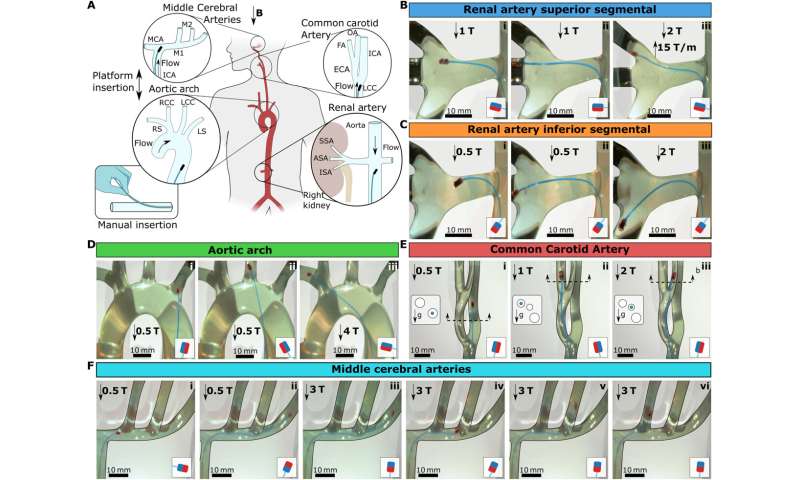
3 d导航下血管生理流。(A)示意图说明三维血管幻影模拟3 d脉管系统。四个不同的血管模型测试:肾动脉,主动脉弓,CCA和差异。图表描绘了插入的导方向,和流箭头显示生理流的入口方向。介绍了导丝通过小插入水管通过聚四氟乙烯管模拟腹股沟访问,左下角所示。(B)导丝引导向上级节段动脉(SSA)。(C)导指导下节段动脉(ISA)。主动脉弓(D)导指导。(E)转向左边CCA置入导丝。横截面上的血管结构给出了左边的每一帧显示3 d对齐的管子和重力方向。 The blue circles in the cross section show the branch guidewire is located. (F) Guidewire steering in MCAs. The magnetic configurations are shown in the small schematic in each frame. Scale bars, 10 mm. Credit:科学的进步(2023)。DOI: 10.1126 / sciadv.adg6438 -
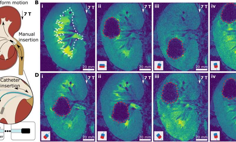
在MRI超高频导指导。(A)示意图说明一个导航实验猪肾的肾腔体外。肾脏是放置在核磁共振成像中心,即。,uniform 7-T magnetic field, and not moved during guidewire steering in the renal cavity. The guidewire was inserted through the urethra. The three target directions and corresponding magnetic tip configurations are shown. (B) MR images of guidewire insertion. The approximate boundaries of the renal cavity were shown with white dashed lines on the preoperational MRI image of the kidney (i). Then, the real-time MR image snapshots of the guidewires with perpendicular (ii), antiparallel (iii), and parallel (iv) magnets were shown in the renal cavity. (C) Supporting catheter-based steering of the guidewire. The three cases of different guidewire free lengths are depicted for antiparallel magnet configuration. The free-length ruler with the supporting catheter is shown at the bottom. (D) MR images of guidewire steering. The guidewire with the antiparallel magnet, as shown in (i) and (ii), with guidewire free lengths of 0 and 20 mm, respectively. The guidewire with the parallel magnet, as shown in (iii) and (iv), with guidewire free lengths of 0 and 20 mm, respectively. The boundaries of the tip magnet MR image artifacts are shown with red dashed lines. The magnetic configurations are shown in the small schematic in each frame. Scale bars, 20 mm. Credit:科学的进步(2023)。DOI: 10.1126 / sciadv.adg6438
前景
这样,穆罕默德Tiryaki和他的同事们介绍了磁性的概念转向与超高磁导领域。他们结合磁性和力学的理论建立设计原则在核磁共振成像扫描仪中改进的指导功能。
物理学家们确定核指导指导在核磁共振成像的可行性通过一系列的3 d导航步骤。他们预计的新方法超高磁场驱动影响临床场景在MRI干预最终促进身体所需情报自动化临床干预实践。
更多信息:穆罕默德Efe Tiryaki et al,在超高磁场磁导的指导,科学的进步(2023)。DOI: 10.1126 / sciadv.adg6438
马丁·弗朗西斯·费兰等热量减轻设计和洛伦兹力转向的核磁共振检测驱动Microcatheter向微创手术,先进的科学(2022)。DOI: 10.1002 / advs.202105352
©2023科学BOB体育赌博X网络


